手持檢測儀器用以調試、分析、監測、故障排除和維修/保養 CAN-Bus - 整合的功能和簡易的操作界面,為 CAN-Bus 上的物理和邏輯分析的新標杆
Possibilities
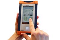
The CANtouch is a mobile measuring device for CAN-based bus systems.
The further development of the CAN-Bus Tester 2 is battery-powered and equipped with a touch display. Its intuitive user interface allows extensive measurements to be taken in the shortest possible time. The results can be archived for documentation or later analysis and further processed on the PC.
The physical layer measurements have been extended to include the direct determination of potential differences between the participants (common mode/ground shift).
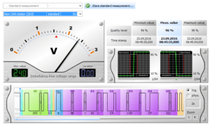
With the online trigger, you can monitor the bus for individual physical limits, determine problems over time and make errors visible in the oscillogram.
The protocol monitor is used for sending, receiving, decoding, and recording messages.

Bus Systems
The CANtouch supports these bus systems in physical layer measurements: CAN, CANopen, DeviceNet, and SAE J1939.
You can also use CANtouch for measurement in other bus systems based on the CAN standard. These include Isobus, NMEA 2000, and SafetyBus P and Energy bus, CANaerospace, and ARINC825. Niche bus systems also include MilCAN and CANopen Lift.
Physical Measurements
- • CAN power supply voltage (with time curve)
- • Shield voltage (with time curve)
- • Common mode voltage (with chart)
- • CAN level difference
- • CAN level absolute
- • Bus wiring
For every node within the bus can be determined additionally
- • General quality level (with min/max evaluation)
- • Edge steepness
- • Disturbance free voltage range
- • Oscillogram display of the messages
- • Logical decoded display of the messages

Protocol Analysis
- • Bus status (with time curve of bus traffic load)
- • Bus errors (active- and passive error frames with min/max and time curve)
- • List of nodes
- • Protocol monitor
- • Send and receive messages
- • Symbolic decoding with individual display
- • Trace for later analysis

Sofware License Model
The big range of functions is not often needed in whole. To set the device to an attractive price worthy level, a license model was established. The not included functions can be tested in a 30 day trial time. At this time, there are no functional limitations. To get a function unlocked forever, a license has to be purchased.
So you are deciding on your own which functions are needed in your case and what is worthy of investing in.
Even the hardware doesn’t have to be purchased completely. The basic set comes without a service case and adapter set.

Device Philosophy
The CANtouch is a battery-operated handheld diagnosis device for physical and logical CAN bus analysis. With its modern touch control, it allows intuitive and efficient handling without an additional computer.
As further development of the CAN-Bus Tester 2, it has not only its functionality; it has new additional measurements as well. An easier valuation procedure with traffic light colors and smileys supports your work with a quick valuation of the measures.
With the possibility for future updates, you are equipped for further enhancement. New functionality can be unlocked by purchasing additional licenses. In addition, we provide new software within the scope of product maintenance, which can be downloaded free of charge by every owner of a CANtouch. Many new functions are made available free of charge.
The integrated battery supplies power to the device without a problem for a whole intense measurement day. It is monitored by a special charge controller that calculates the remaining time and residual charge. If all that is not enough – the device is charged up to 80% in only one hour regardless of whether you are measuring at that time or not.
The rubberized aluminum continuous casting body is not only impressing high quality, but it is also extremely robust.
Rating System 

With traffic light colors red, yellow, and green plus a display as smiley, you gather rapidly how your system is doing today.
By clicking on the smiley, it shows the basis of valuation.
You can set the threshold values via an XML file to make individual specifications for the evaluation. You have always loaded the appropriate rating file for your system after a one-time setup through the project management.
Bus Settings 

After selecting the right bus system, you have more options for choice. The device is searching for the correct baud rate, but it is also possible to choose one by hand. Beyond that, you can change the bit timing, which is essential for systems that are not running on CiA standards.
Besides this, you should choose the right ground reference point, whether the external ground connection or CAN_V- which is connected to pin 6 of the 9‑pin sup D socket.
Your settings for the CAN bus are saved project-related.
Control Center

In the control center, you can quickly reach the most important settings.
- • Language switching
- • Keypad sound
- • Screenshot
- • Automatic brightness
- • Basic setting Brightness
- • Baud rate
- • Baud rate scan
- • Jump to the Bit timing menu
- • List Only /Bus Actual switching
- • A changeover of the mass reference point
- • When using projects: Display the active project and jump to the project management
Other Settings

The settings menu includes the following items:
- • Device information
Firmware management, battery status, memory usage, licenses, manufacturer information - • Device settings
Language, brightness, switch-off delay, time - • Project management
Creating, deleting, and naming projects
Project-related bus settings
Project-related screenshots
Project-related rating settings - • A possibility to reset the device to factory settings
Archive Measurements 

You can store the measurements of single nodes and the results measured by the apps Bus Wiring and Online Trigger in an archive file in a folder of the device’s flash drive. So they can be opened and analyzed later on by the device itself or a computer. You need the CAN-Bus Tester 2 user software, which is freely downloadable on this website for importing to the computer.
Besides that, you can save screenshots for documentation of all other measurements. More about that in the next menu item.
Screenshots

The CANtouch can save up to 100 screenshots per project.
Simultaneously pressing the buttons “Power” and “Home,” another screenshot is made and saved to the flash drive. You can also access this function via the control center. If you reach the maximum number of screenshots, the device will delete the oldest.
With this feature, you can report the device’s functions and all measurements. The png-format files can be opened or imported into many software and documents.
Help

The CANtouch shows information to the chosen feature if you tap that button.
Technical Data
-

CANtouch
• General parameters and overview of functionsBus systems
CAN (ISO11898‑2), CANopen (CiA301), DeviceNet (EN 50325 – 2), SAE J1939
Bit sampling
64-fold, 10240 sampling points
Bit timing
Adjustable BTL cycles (tq), sample point and resynchronization jump width (SJW)
Supported baud rates
Depending on bus system: 10; 20; 50; 100; 125; 250; 500; 800; 1000 kbit/s
Additionally user-defined: 5; 33.3; 62.5; 75; 83.3; 200 kbit/s
Automatic detection via baud rate scan, bit timing adjustableBus status
Bus traffic detection (display: dominant, recessive, not defined, bus traffic)
Display of the Bus traffic load (0 … 100 %)
characteristic, minimum and maximum value savingBus errors
Display of detected frame errors
Distinction between active and passive error frames (0 … >50,000), trend chartBus voltages
Display of the optional CAN supply voltage and shield voltage
Characteristic, minimum and maximum value savingCommon mode voltage
Acquisition of the maximum voltage offset between the individual bus nodes
CAN level (absolute /differential)
Acquisition and evaluation of the differential and absolute CAN levels of all bus nodes during operation
Node measurement
Node related measurements
Quality value (signal quality), Disturbance-free voltage range, Edge steepness (falling
and rising) and Oscilloscope display with message frame analysisOnline Trigger
Error analysis with adjustable values, variable time slices and trigger function
Protocol monitor
Send and receive of CAN messages
• Electrical parameters
Power supply and battery*
Integrated, rechargeable lithium-ion battery
External power input: SELV d.c. voltage 14 V, internal fused with 2.5 A
Operating with the supplied 35 W wide-range power supply unit only (SAW-14.0 – 2500)
Times-to-empty: Standby: up to 500 hours
Use: up to 36 hours
Measuring: up to 6 hours
Charge times: Quick charge to 80% in approx. 1 h
Full charge in approx. 2 hPotential difference between the CAN bus and USB connections
< 500 V AC
Voltage between any two terminals of the CAN connection or external ground, resp.
< ±30 V DC
Measurements
Range
Resolution
Accuracy (typ.)
Quality value
0.0 % … 100.0 %
0.1 %
-
Edge steepness
0/64 … 64/64
1/64
-
Disturbance-free voltage range
-0.75 V … +3.25 V
0.05 V
1.90 % ±100 mV
Measuring of the differential voltage
-0.75 V … +3.25 V
0.01 V
0.50 % ±10 mV (calibrated)
Measuring of the absolute voltage
-5.00 V … +10.00 V
0.05 V
0.50 % ±50 mV (calibrated)
Measuring of the shield voltage
-10.0 V … +1.0 V
0.1 V
0.25 % ±100 mV (calibrated)
Measuring of the CAN supply voltage
0.0 V … 32.0 V
0.1 V
0.25 % ±100 mV (calibrated)
Measuring of the loop resistances
0 Ω … 100 Ω
100 Ω … 1000 Ω0.1 Ω
1.0 Ω0.85 % ±0.2 Ω
0.85 % ±2.0 ΩMeasuring of the cable length
2 m … 1000 m
1 m
5 % ±2 m
(signal propagation delay: 4.5 ns/m)• Mechanical parameters
Power supply unit connection
Extra-low voltage socket
CAN connection
9‑pin D‑Sub connector
PC connection
Self-powered device to USB Specification 2.0, full speed, in addition, electrically isolated
Connection of a drive for exchange of measuring data (USB mass storage device)Housing
Aluminum housing, cover glass
Ambient conditions
Operation temperature: 5 °C … 40 °C
Storage temperature: ‑20 °C … 60 °C
Atmospheric humidity: 20 % … 80 %, non-condensingDegree of protection of the housing
IP20 to EN 60529
Dimensions
186 mm x 102 mm x 37 mm
Weight
Approx. 860 g